Like many, I was surprised to learn after purchase that my $40k+ car did not come with a factory alarm. I did not want to go aftermarket since there are no recommended remote start options for BMW, so I decided to retrofit the OEM alarm.
Total cost for this ended up being around $180 USD, not factoring the extra money recovered from selling the original Roof Module. Patience and waiting for finding good deals on the auction sites makes it much more reasonable than buying parts new.
DISCLAIMER: As with all DIY projects, undertake this at your own risk. I am not responsible for anything that happens to you or your car! With that said, on to the write-up!
Pre-Requisites: About the only thing you need to make sure your car has is a mirror that has the alarm LED dome. Most US model F30s should already have this. If yours does not, you will need to replace your rear-view mirror. Additionally, this retrofit requires you to have E-Sys(for coding the replacement module) and Rheingold/ISTA(if equipped with Sunroof, as you will need to re-initialize your sunroof once you install the new roof console)
OPTIONAL ADDITIONS: With this retrofit, there are 2 additional optional items that I opted not to do, that you can do if you so desire:
- Replacement Key Fobs You can obtain replacement Key Fobs that have the Panic Button
- Replacement Door Latches The F30s that include the factory alarm feature the dead-locking doors which, when the doors are locked via remote/Comfort Access, make it so that the doors cannot be opened from the inside. Those in the U.S. without the factory alarm likely do not have this feature. Easiest way to test is to roll down your windows, lock the door via remote, then without the key on or near you, try to open a door by reaching inside and using the interior door handle. If it opens, you do not have the dead-locking door latches. Not having these type of door locks does not affect the alarm function at all, as I tested it by doing the above and the alarm will trigger. You can opt to replace these with the dead-locking door latches for around $150.00(total for all 4 doors) if you buy them used online. Replacing these does not require re-keying the car, as it doesnt change the key cylinder, just the part inside the door that latches to the body of the car when the door is closed.
Parts List: (Note: Part #s may vary per vehicle. Parts listed below are for a US F30 sedan. Check RealOEM or ETK to confirm correct Part #s for your vehicle)
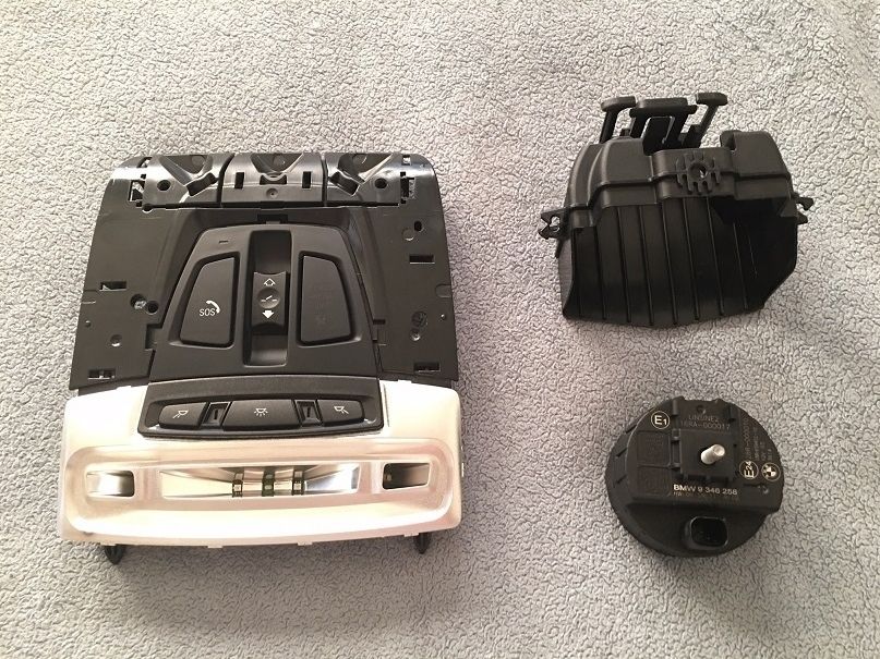
- Roof Function Center There are several variants of this part depending on if your car has a Sunroof or the Teleservices/SOS call button, which can be seen
here on RealOEM. Since I had both of those options, I used part #61319351186.
- Alarm Siren 65759198581(there are several different part numbers for this, any of them should be fine)
- Bracket, Alternative Power Siren 65759224277
- Hex Nut - Qty. 1 07129904870
- Rep. Kit for Socket Housing Qty. 1 61132359998
- Socket Contact w/ Grommet Qty. 3 - 61130005199
- Bushing/Socket Contact Qty. 3 61130005197
- Double Leaf Spring Contact Qty. 1 61130007437
- OEM Wire Tap Qty. 1 - 61138364566
 Tools Required:
- Jack/Jack Stands/Lug Nut Tool
- Socket Set with 10mm and 8mm sockets
- Hex/T set This project requires a T-35/T-40 bit for removing the Trunk Lining
- Flat Screwdriver/Pry tool for removing the plastic expanding rivets
- Wire Stripper
- Wire connectors/solder depending on your preference
- 3 different colors of 18 gauge wire (alternatively, you can use different color electrical tape/labels to identify wires)
- Standard black electrical tape
- 2 additional colors of electrical tape (I used Red and Yellow during this retrofit)
Prep Work:
- Disconnect Negative Terminal from Battery Make sure sunroof is closed(if equipped), all doors are unlocked, and trunk is open first
- Remove the Left Side Trunk Lining
- Next, jack up the left side of the car at the front and place a jack stand under the left rear jack point
- Remove the left rear wheel
Creating the Siren Wiring:
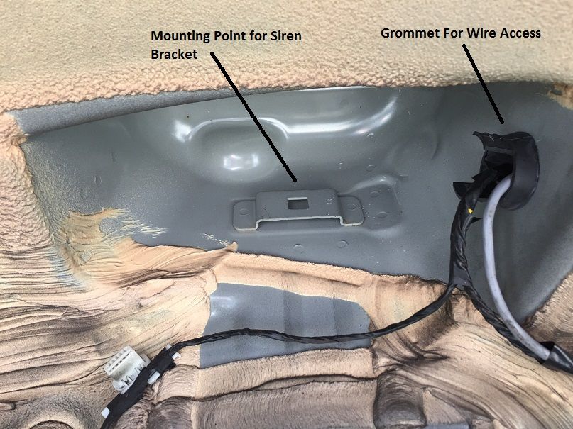
- With the left rear wheel removed, use the Socket Set and the pry tool to remove all of the expanding rivets and nuts from the wheel well lining. Once all are removed, pull down to remove the lining from the car
- You should now be able to look up and see the space where the siren will be installed. To the right of that space, you should also see a large black grommet where the existing wiring runs to the inside of the car, as shown below
- Now, you will need to create a harness using the 3 different color wires. For the purpose of the rest of the write-up, I will be referencing the colors I used, which are Red(power), Black(ground), and Yellow(signal)
- Wrap about 1 foot of the wires together using black electrical tape
- Next, using a screwdriver, punch a hole in the black grommet to make an opening for the wire harness to run through
- STARTING FROM INSIDE THE CAR, push the wire harness through to the outside of the car
- Once you have the wires through the grommet, you can now attach the three socket contacts w/ grommets to the harness, and then attach them to the connector. As I attached each contact, I would then connect it to its proper connector slot so as not mix up the wires. Wire connections are as follows:
- Red(Power) to Pin Slot #3
- Black(Ground) to Pin Slot #1
- Yellow(Signal) to Pin Slot #2
- Once you have inserted the wires into the connector, finish wrapping the connectors with some electrical tape/heat shrink to secure them together
Mounting the Siren:
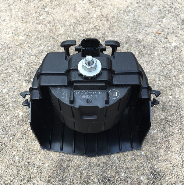
- Mount the siren to the Bracket using the Hex Nut and tighten it in place. It will only properly fit in one direction, as shown below:
- Next, connect the Siren Wire Harness to the Siren, then slide the siren bracket up into place inside the wheel well
- Once the Siren is in place, you can replace the wheel well lining and all plastic rivets/nuts
- Replace the left rear wheel and lower the car, remembering to tighten the wheel once lowered
Connecting the Siren Wiring:
- The connecting point for the Black(ground) wire is actually very close to where the wires enter the car, as shown below:
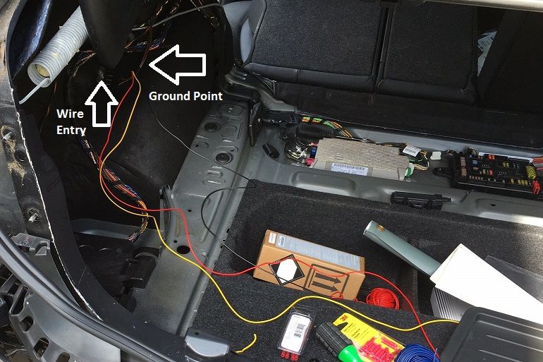
- Using an OEM wire tap, connect the Black(ground) wire to one of the medium sized Brown ground wires, as shown below:

- Next, run the Red(Power) wire along the wiring bundle across the trunk floor to the Rear Fuse Block, which is located on the far right side of the first picture above
- Remove the 10mm Hex Nut to loosen the Fuse Box
- Connect the Double Leaf Spring Contact to the Red(power) wire, then insert the contact into the slot for Fuse F103. On my car, even though there was no existing wire in the slot for F103, there was already a 5A Fuse present. If yours does not have a 5A Fuse in the slot, then you will need to obtain one
- Lastly, begin the process of running the Yellow(Signal) wire towards the front roof control panel. You can choose to either run it up the C-Pillar and then along to the front of the car, as I did, or you can run it along the bottom of the car and then up the A-Pillar. The preference is yours.
Installing the new Roof Function Module and Wiring:
- Start by removing the old roof module by using your fingers to pull down on the trim panel towards the sunroof area
- Once the trim is removed, you will notice one small rectangular hole on each side. Use the flat headed screwdriver to push the clip inside that slot towards the middle of the module while pulling down to release it. Repeat for the other side
- Now that the module is loose, disconnect all wiring harnesses from the module
- Next, pull apart the trim above the rear view mirror to expose the wiring connector for the mirror
- The picture below shows the open space from the roof module, as well as the wiring path and where the wires will be run to: (note: removing the rear-view mirror is not necessary, it just made it easier to handle the wiring)

- Finish running the Yellow(Signal) wire as shown, and then connect one of the Socket Contacts to the end of the wire. Insert the connector into Pin Slot #11 of the Large 16 Pin Black connector that attached to the right side of the Roof Module(not shown in the above picture).
- Next, take the remaining two Socket Contacts and connect them together in the middle
- Insert one connector end into Pin Slot #3 of the same Large 16 Pin Black connector that you inserted the signal wire into
- Run the wire along the red path shown above, and insert the other end into Pin Slot #9 of the Black 10-Pin Mirror connector
- Replace the mirror trim pieces
- Reconnect all wiring harnesses to the New Roof Function Module, and then carefully insert it into place and reattach the trim piece.
At this point, all connections are completed and everything physically should be in place, now on to the coding!
Vehicle Coding:
- Reconnect the Negative Battery Terminal to restore power to the car
- Connect to the car via E-Sys. After connecting, the first step will be to add Option 302 to your FA. Follow the steps in the E-Sys learning guides if you are unfamiliar with how to complete this step
- Once you have updated your FA with the new option code, you will need to create 2 new Cafd files for your new FZD(roof) Module. However, you will need to know your cars current I-Step Level first
- To find this, go to the Expert Mode-VCM Screen. Under I-Steps, click Read. Your current I-Step level will then be displayed, as shown below. Take down this information, and save for future reference if needed.
SHOWN FOR ILLUSTRATIVE PURPOSES ONLY:

- Now, you can create the CAFD files. On the Expert Mode-Coding screen, if you click Read (ECU), you should now see the FZD listed as one of the modules on your car. However, it will be missing the CAFD files. Highlight the FZD, then click Detect CAF for SWE. When the window shown below comes up, you may have several options available:
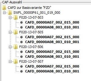
- You will need to select the option that matches your cars current I-Step Level, or is close to it(My I-Step level is F020-13-03-503, however that option was not listed. So I chose the one that also ended with 503 and had no issues). NOTE: The FZD requires both CAFD Files to be present. After finding the correct I-Step Level, hold down CTRL and select both CAFD options, and hit Ok. This will create the CAFD files for the FZD.
- Now all that is left is to VO Code the updated FA to the car. Activate the FA. At a minimum, you will need to code the FZD, REM, HU_CIC/NBT, and FEM modules. Personally, whenever I complete a retrofit, I code the new FA to all modules in the car in the event that there is something related to the new retrofit in that module that may have been missed. How you code is up to you, but by coding them all, it avoids the risk of missing something.
Sunroof Initialization(Only required if your car is equipped with a Sunroof):
Connect to the car via Rheingold/ISTA. Once you have connected, you will go to Service Functions -> Body -> Locks -> Sunroof Initialize, and follow the on screen prompts to re-initialize the Sunroof, as it will not function without this step being completed.
Testing/Reassembly of the car:
Once you have completed all coding, turn the car off, and exit the vehicle. If you press lock/unlock on the remote, you should now hear the audible sound when the car locks/unlocks. You can also test the alarm as I described above in the Optional Additions section. Once you are satisfied that it works, you can replace any remaining trim pieces in the car, and you are all done!
Congrats! You now have a functional OEM alarm for your F30!